Chapter 23 Magnetic Flux and Faraday’s Law of Induction 23.1 Induced EMF 23.2 Magnetic Flux 23.3 Faraday’s Law of Induction 23.4 Lenz’s Law 23.5 Mechanical Work and Electrical Energy 23.6 Generators and Motors 23.7 Inductance 23.9 Energy Stored in a

Chapter 23 Magnetic Flux and Faraday’s Law of Induction 23.1 Induced EMF 23.2 Magnetic Flux 23.3 Faraday’s Law of Induction 23.4 Lenz’s Law 23.5 Mechanical Work and Electrical Energy 23.6 Generators and Motors 23.7 Inductance 23.9 Energy Stored in a

I need to know the power of a motor in Hp required to move a vehicle of about 150 Kg. The vehicle is equipped with gear assembly and required to run at 20 to 25 Km/h. This has to be converted to
Moving a magnet towards a coil produces a time-varying magnetic field inside the coil The induced emf in a coil of N turns is equal to Energy Method: Look at change in stored energy to calculate force H C ·dl =I enclosed B S ·dA =0 f =q v ×B B [Wb/m 2 H ...
Instantaneous auto switching between power sources. ABB offers a wide selection of auto transfer switches (ATS), from 160 to 1600 Amperes in range. They have the features and functionality that makes them suitable for diverse applications: industrial
Transformer in physics is described as a device that is used in the power transmission of electric energy. Learn more about the working principle, types along with diagrams. The transformer in the simplest way can be described as a thing that steps up or steps
8/9/2018 · Electrical power consumed by a resistance in an AC circuit is different to the power consumed by a reactance as reactances do not dissipate energy. In a DC circuit, the power consumed is simply the product of the DC voltage times the DC current, given in watts. However, for AC circuits with reactive components we have to calculate the consumed
Definition of Relay Terminology • Life Curve This is listed in the data column for each type of relay. The life (number of operations) can be estimated from the switching voltage and switching current. For example, for a DS relay operating at: Switching voltage = 125V
transfer power from the primary winding to the other windings with no energy storage or loss. For HW# 1 show the B-H curve for a transformer with transferred and core loss energy indicated. The choice of circuit topology obviously has great impact on the
25 V 500 V 1 kV 2 kV 4 kV Req = 42 0.6 A 12 A 24 A 48 A 96 A Req = 12 2.1 A 42 A 84 A 167 A 334 A Req = 2 12.5 A 250 A 500 A 1000 A 2000 A L N PE Decoupling network Combination wave generator AC (DC) power supply network Rext = 0 Ω L
Additional parts can be used to expand a trolley system or build your own trolley system. Minimum required cable/hose length is based on 6 ft. of cable or hose between trolleys plus an additional 7 1/2 ft. at each end. Warning: Never use to lift people or items over people. For 0.4" to

1. Max. switching power (AC resistive load) 2. Max. switching power (DC resistive load) 3. Coil temperature rise Sample: ALZ11F12, 5pcs. Measured portion: coil inside Contact current: 0 A, 16 A 1310 01000 1 10 16 100 100 440 Contact voltage, V 0 10 1 10 100
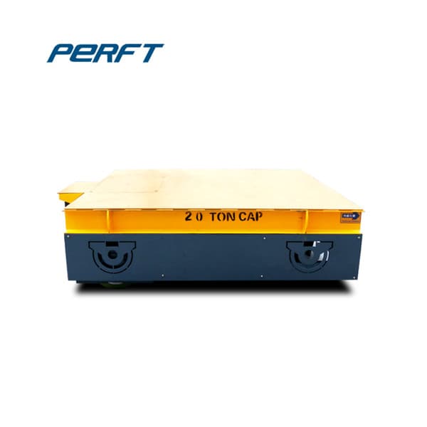
11/8/2021 · Note 17: This is the calculated coil power dissipation (in watts) for the DC current case. High power dissipation will increase the copper wire temperature and the resistance as discussed in Note 11. Note 18: If the coil is driven by an AC driver such as the TS250, the RMS power dissipation is calculated using the user input (peak) current to calculate the RMS current and then calculate the
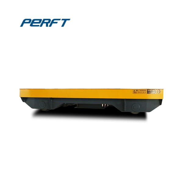
The Golf Trollley Store is the leading electric golf trolley Sales & Service centre in the UK or Ireland. Spare, repairs and sales for all makes and models of electric golf trolleys

Search the world's information, including webpages, images, videos and more. Google has many special features to help you find exactly what you're looking for. Advertising Programs Business Solutions About Google Google.com

W/(m 2 K) Btu/(ft 2 o F h) Tubular, heating or cooling Gas at atmospheric pressure inside and outside tubes 5 - 35 1 - 6 Gas at high pressure inside and outside tubes 150 - 500 25 - 90 Liquid outside (inside) and gas at atmospheric pressure inside (outside) tubes